
FTTx Access Rollouts
Coordinate feeder cables, branching closures, splitter positions, distribution boxes and final drop connections. Record planned subscribers, split ratio, spare capacity and the end-to-end loss budget.
Access components →Explore connected product requirements for access, campus, data-room and telecom environments. Each scenario starts with the route, interfaces and maintenance conditions.
Use these starting points to assemble a coherent product list rather than separate enquiries with incompatible interfaces.
Coordinate feeder cables, branching closures, splitter positions, distribution boxes and final drop connections. Record planned subscribers, split ratio, spare capacity and the end-to-end loss budget.
Access components →Connect buildings with a defined cable route, termination plan and equipment interface. Confirm duct or aerial construction, internal cable transition and the acceptance measurements.
Build a route schedule →Bring patching, rack depth, fiber raceways, cable trays and branch power into one equipment layout. Leave working space for moves, additions and connector inspection.
Rack and pathway topics →Match transport fiber, site cabinets, DC power distribution and equipment clearances. Include cable entry, heat load, grounding and access restrictions in the site schedule.
Telecom power topics →Check exposure, route separation, enclosure construction and service availability. Where resilience matters, document the redundant path rather than relying on a product label.
Cable selection topics →Plan transportable or protected equipment housing around installation access, power interfaces, thermal needs and recovery. Identify which components must be replaceable in the field.
Outdoor infrastructure topics →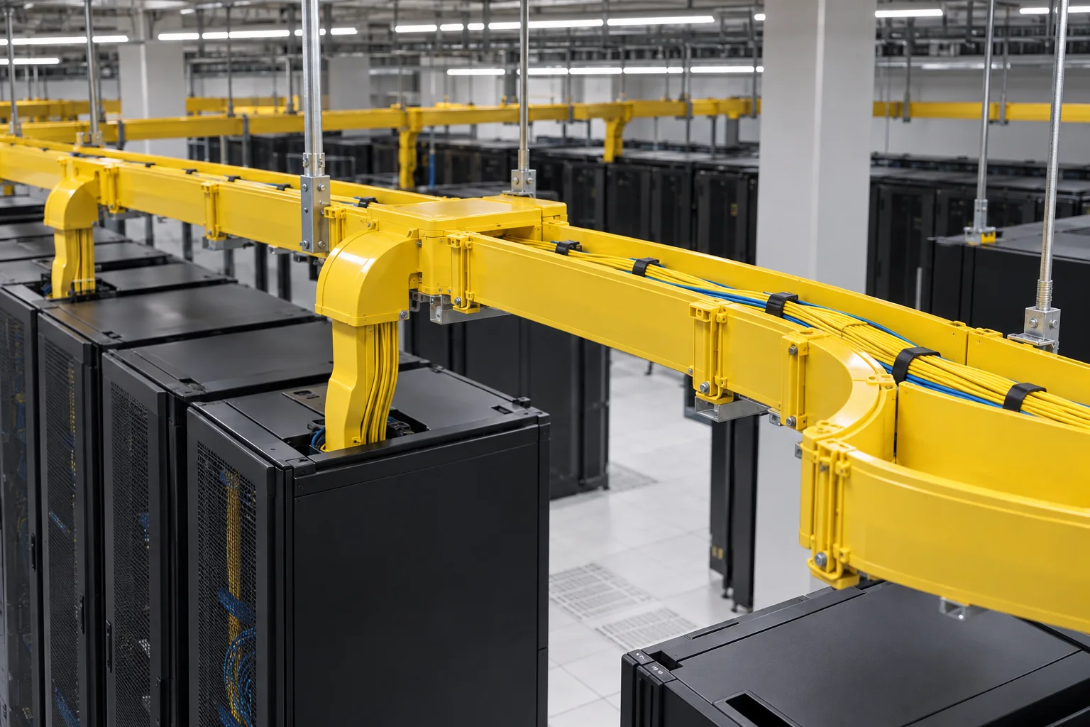
Overhead raceways, patch panels and equipment ports meet at the same rack. Their positions determine cable approach, slack storage, bend control and how easily a technician can reach the connection.
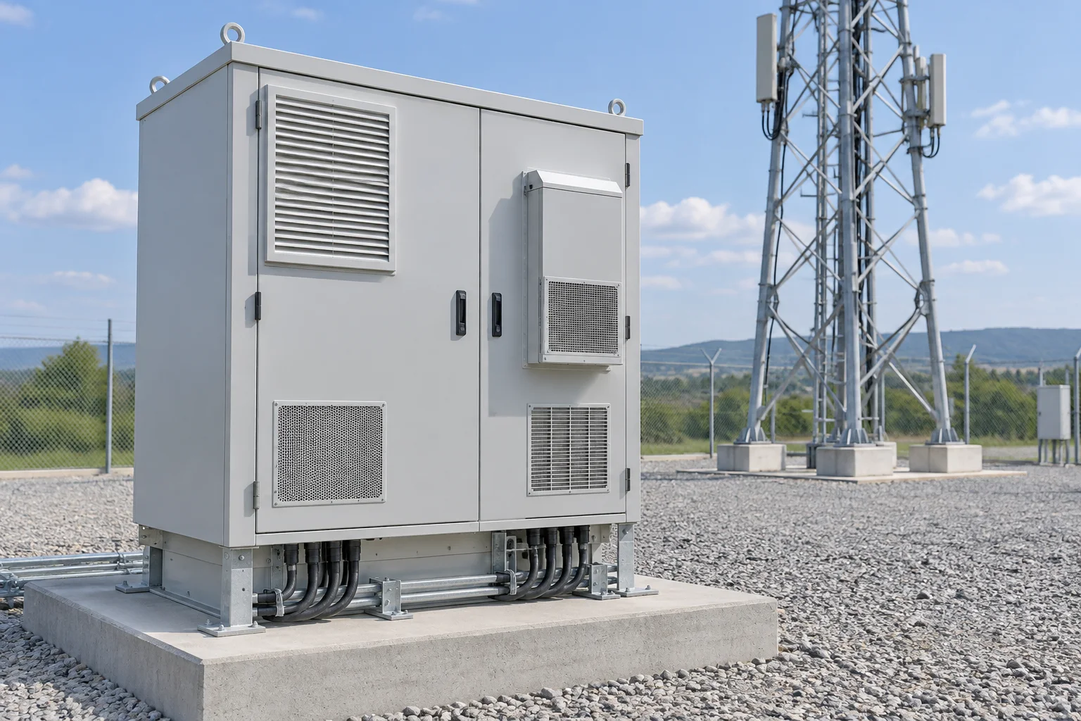
Outdoor requirements depend on more than a cabinet dimension. Temperature, solar exposure, coastal conditions, water paths and maintenance access affect materials, sealing, cooling and the internal arrangement.
Use one set of site assumptions for the fiber, rack, enclosure and power enquiries.
Country, site type, route, environment and service access.
Capacity, equipment list, topology and interface schedule.
Mounting, cable entry, installation and maintenance method.
Design stage, target delivery and required acceptance evidence.
Tell us which fiber, rack, enclosure or power decisions need to be reviewed together.